A time relay (also known as a timer relay) is an electronic component used in electrical circuits or machine control systems to control power contactors based on time parameters. Time relays automatically manage the start of circuit/machine operation and stop the system when the preset time expires. Time relays are circuit elements designed with multiple timing modes, features, and functional variations. You can find detailed information about time relay types, specifications, working principles, and wiring logic in the rest of this article.
What Are the Types of Time Relays?
Time relay models stand out with designs engineered for different automation functions. Their main operating modes include:
On-Delay Timer Relay (Pull-In Delay)
These models begin counting time immediately when voltage is applied to the coil. When the preset time ends, the relay automatically disconnects from the circuit. This type is also referred to as a standard (forward) time relay.
Off-Delay Timer Relay (Drop-Out / Reverse Delay)
These models change the contact position only after coil power is removed and the preset time expires. They are also known as reverse time relays.
Release-Delay Timer Relay (Latching + Return Delay)
The relay pulls in instantly when energized, stays in the active position during timing, and returns to its original (initial) state when the preset time ends.
Star-Delta Timer Relay
These relays are commonly used for high-power industrial motors. When energized, they provide a star connection at first, then switch to delta mode after the preset delay, supporting a safer motor start topology.
Flasher Timer Relay (Oscillating ON/OFF Timer)
These models start oscillation when voltage is applied to the coil, maintain position for the preset time, and return to the initial state when time ends. As long as the coil remains energized, the ON/OFF cycle continues automatically.
Asymmetric Flasher Timer Relay
These models include two independent timing parameters. Coil energization causes the contacts to toggle positions at different timing intervals.
What Does a Time Relay Do?
Time relays play a critical role in industrial and building automation by managing time-based switching tasks. They prevent current from exceeding the specified ampere rating, operate in series with the load, and provide system protection during overload, short circuit, or unstable voltage conditions. Example use case: a time relay can activate or deactivate a heating system at specific temperature or time cycles. While improving operational reliability and circuit safety, time relays also deliver a major advantage in energy efficiency and controlled automation.
How Does a Time Relay Work?
Time relays operate with a simple timing + scanning loop logic:
In on-delay models, the timer begins when the coil is energized.
When the preset time ends, the relay changes contact state:
A normally open (NO) contact closes,
A normally closed (NC) contact opens.
In off-delay models, the contact state changes instantly when energized, but does not return until coil power is cut and the preset time finishes. The cycle time depends on the internal clock speed, program length, and coil/contact architecture. Typical scan cycle duration in industrial timer relays is approximately 3–10 ms, depending on command complexity and timing circuitry.
Where Are Time Relays Used?
Time relays are used in a wide range of engineering applications, such as:
Agricultural and garden irrigation systems: timed pump control
Industrial process automation: conveyor lines, production sequencing
Public outdoor/indoor lighting systems: parks, streets, hospitals, schools, mosques
School signaling systems: bell timing intervals
HVAC automation: periodic heating/cooling control
Automotive systems: motor control coordination in embedded automation
What to Consider When Selecting a Time Relay?
Key engineering criteria include:
Correct timing mode support (on-delay, off-delay, flasher, star-delta, asymmetric, etc.)
Supply voltage compatibility with the control/command circuit feed
Required contact count and topology (NO/NC combinations based on design needs)
Device size compatibility with the mounting environment
Trimpot or display clarity for timing adjustment (display-based models are preferred for easier diagnostics)
LED indicators for timing and contact state visibility
Price-performance balance aligned with the project budget
How to Wire a Time Relay?
When connecting a time relay, the installer should:
Follow the terminal legend and schematic printed on the relay body,
Match coil input, load output, and trigger terminals exactly to the wiring diagram,
Ensure compliance with the manufacturer installation guide for safe and correct wiring.
The wiring diagram indicates which terminals receive coil voltage, which connect to the load, and which handle timing feedback or triggers. For proper and safe installation, the manufacturer’s technical documentation must always be followed.
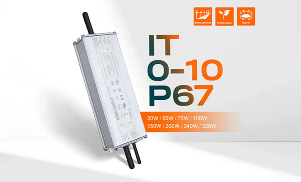
Inventronics has announced two new additions to its outdoor LED driver portfolio: the 150W IT 0-10 150/100-277 P67 and the 240W IT 0-10 240/100-277 P67 programmable drivers. With this new series, the company aims to establish a new benchmark in street and area lighting in terms of performance, efficiency, and durability.
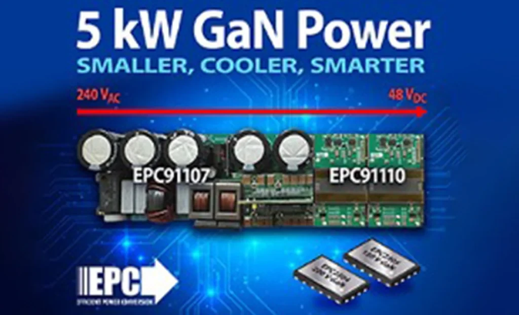
5 kW GaN-Based AC/DC Reference Design from EPC for AI Servers and Data Centers EL SEGUNDO, California — October 2025 — Efficient Power Conversion Corporation (EPC), the world leader in enhancement-mode gallium nitride (eGaN®) power devices, has announced a high-efficiency, high-power-density 5 kW AC-to-48 V DC GaN reference design developed to meet the demands of AI servers and next-generation data center power architectures.
Sensirion has officially announced its next-generation SEN65 and SEN63C sensor platforms, designed to make indoor air quality measurement easier and more accurate than ever before. In addition, the SEK-SEN63C evaluation kit is now available for purchase, enabling developers and system integrators to quickly test and evaluate the new sensor family. Initial orders can be placed immediately.
The long-awaited beta release of Vitis AI 5.1 from AMD has been announced, marking the beginning of a major architectural shift that significantly advances edge AI inference capabilities.
With 44 years of experience, Empa Elektronik, a trusted and pioneering company in the electronic components industry, is set to make transformative investments in the technology ecosystem through its collaboration with Fark Labs, a global innovation and transformation center.
In a comparative study of Auto-ML platforms designed to simplify edge AI deployment, NanoEdge AI Studio and Edge Impulse emerged as leading solutions [1]. The comparison was conducted using multi-sensor biomedical data applied to predictive maintenance use cases.
In shopping malls, galleries, and large-scale commercial spaces, the stability and intelligence of lighting systems are among the most critical factors directly influencing user experience.