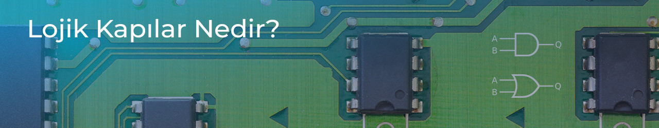
Logic gates are electronic circuits that contain one or more inputs and a single output. They are also known as logic circuits or digital (Boolean) gates. Logic gates are built from fundamental electronic components such as diodes and transistors, and they operate according to predefined Boolean (algebraic) logic rules. In sequential or combinational digital systems, logic gates process input signals and produce logical results based on Boolean functions. Their core purpose is to evaluate digital states (1/0, HIGH/LOW, TRUE/FALSE) and maintain or change circuit behavior accordingly.
What Are the Main Logic Gate Circuits?
There are 3 primary logic gate topologies:
AND (logic product / intersection)
OR (logic sum / union)
NOT (logic inversion / complement)
These gates form the foundation of combinational logic design and truth-table-driven decision systems.
AND Gate (AND / Logic Product)
Contains 2+ inputs and 1 output
Formula: Y = A . B
Principle: The output can be 1 (HIGH) only when all inputs are 1
Truth table behavior: Equivalent to series-connected switches, all closed = output 1
OR Gate (OR / Logic Sum)
Contains 2+ inputs and 1 output
Formula: Y = A + B
Principle: Output is 1 if any input is 1
Truth table behavior: Equivalent to parallel-connected switches, at least one closed = output 1
Limitation: Not suitable for high-voltage load intersection logic (that role belongs to derived gates like NAND/NOR + protection circuits)
NOT Gate (Inverter / Complement Gate)
Contains 1 input and 1 output
Formula: Y = A’
Principle: Output is the inverse of the input
Input 1 → Output 0
Input 0 → Output 1
Derived Logic Gates (Composite / Generated Gates)**
In addition to the 3 core gates, 4 more gates are derived from them:
NAND Gate (NOT + AND Gate / Inverted AND)
Contains 2+ inputs and 1 output
Formula: Y = (A . B)’
Principle:
All inputs 1 → Output 0
Any other combination → Output 1
NOR Gate (NOT + OR Gate / Inverted OR)
Contains 2+ inputs and 1 output
Formula: Y = (A + B)’
Principle:
All inputs 0 → Output 1
Any other combination → Output 0
XOR Gate (Exclusive OR / Inequality Detector)
Contains 2 inputs and 1 output
Formula: Y = A’ . B + A . B’
Principle:
Output is 1 only when inputs are different (1/0 or 0/1)
All inputs 1 → Output 0
All inputs 0 → Output 0
XNOR Gate (Exclusive NOR / Equality Detector)
Contains 2 inputs and 1 output
Formula: Y = A’ . B’ + A . B
Principle:
Output is 1 when inputs are equal (1/1 or 0/0)
All inputs 0 → Output 1
All inputs 1 → Output 1
Common Engineering Use Cases
Logic gates are used in industrial, embedded, consumer, and safety-critical automation systems. Examples include:
Gate Type Typical Engineering Application
AND Security interlock systems, multi-sensor validation, conditional machine start
OR Lighting circuits, redundant activation paths, multi-switch user controls
NOT Level-triggered pump start/stop logic, inverted control systems, digital logic negation
NAND Overload protection logic, motor driver shutdown interlocks, fault-inversion automation
NOR Digital lock defaults, system-off validation, inverted parallel interlocks
XOR Signal inequality detection, encoder direction change validation, parity check logic
XNOR Equality detection, synchronized input validation, motor phase/state matching
These logic applications support non-permanent prototyping, feedback-based automation, fault protection, signal routing, parity control, direction detection, and timed or conditional process control.
Hardware Used in Basic Flip-Flop / Gate Prototyping
A basic low-voltage memory test circuit may include:
Breadboard
9 V battery + battery holder
Jumper cables
2 × BC237 transistors
2 × 100 µF capacitors
2 × 5 mm LEDs
2 × 10k resistors
2 × 470 resistors
(Brand names such as Arduino and Raspberry Pi remain unchanged in practical use.)
Why Do We Need Logic Gates?
Logic gates enable:
Digital state evaluation
Combinational decision logic
Sequential memory logic
Protection inversion logic
Directional validation
Equality/inequality detection
Fault-safe circuit control
Redundant signal routing
Microcontroller-based analog control via PWM
Industrial automation and interlock reliability
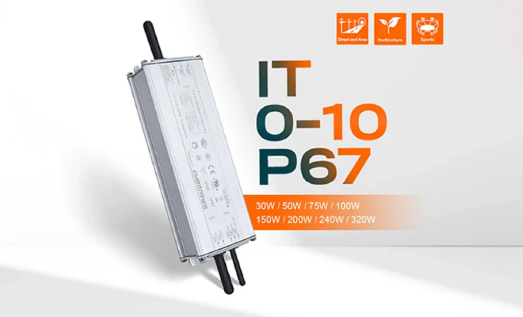
Inventronics has announced two new additions to its outdoor LED driver portfolio: the 150W IT 0-10 150/100-277 P67 and the 240W IT 0-10 240/100-277 P67 programmable drivers. With this new series, the company aims to establish a new benchmark in street and area lighting in terms of performance, efficiency, and durability.
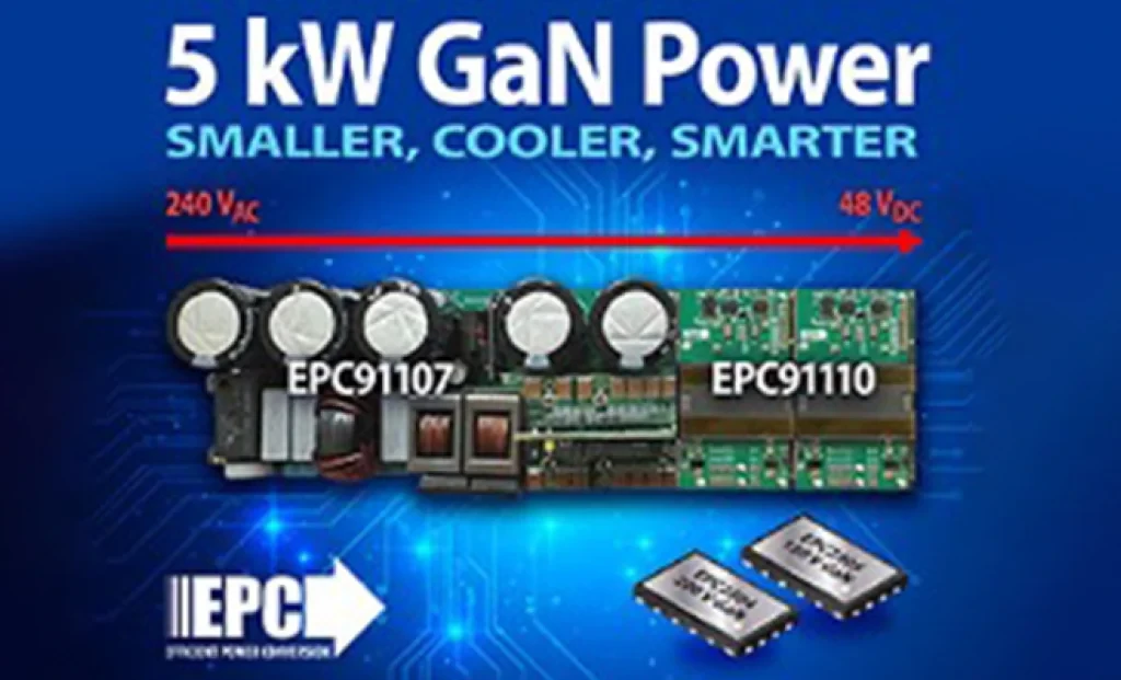
5 kW GaN-Based AC/DC Reference Design from EPC for AI Servers and Data Centers EL SEGUNDO, California — October 2025 — Efficient Power Conversion Corporation (EPC), the world leader in enhancement-mode gallium nitride (eGaN®) power devices, has announced a high-efficiency, high-power-density 5 kW AC-to-48 V DC GaN reference design developed to meet the demands of AI servers and next-generation data center power architectures.
Sensirion has officially announced its next-generation SEN65 and SEN63C sensor platforms, designed to make indoor air quality measurement easier and more accurate than ever before. In addition, the SEK-SEN63C evaluation kit is now available for purchase, enabling developers and system integrators to quickly test and evaluate the new sensor family. Initial orders can be placed immediately.
The long-awaited beta release of Vitis AI 5.1 from AMD has been announced, marking the beginning of a major architectural shift that significantly advances edge AI inference capabilities.
With 44 years of experience, Empa Elektronik, a trusted and pioneering company in the electronic components industry, is set to make transformative investments in the technology ecosystem through its collaboration with Fark Labs, a global innovation and transformation center.
In a comparative study of Auto-ML platforms designed to simplify edge AI deployment, NanoEdge AI Studio and Edge Impulse emerged as leading solutions [1]. The comparison was conducted using multi-sensor biomedical data applied to predictive maintenance use cases.
In shopping malls, galleries, and large-scale commercial spaces, the stability and intelligence of lighting systems are among the most critical factors directly influencing user experience.