Flip-flops are essential circuit components used across many electrical and electronic applications by both amateur and professional designers. A flip-flop circuit can be described as a memory (storage) element built using logic gates. Flip-flop circuits are bistable components, meaning they have two stable output states. They feature dual outputs and retain their output state as long as the input signal remains unchanged. Flip-flops—commonly abbreviated as “FF”—are used to store binary data. Detailed information regarding flip-flop types, operating principles, and circuit behavior can be found in the rest of this article.
What Does Flip-Flop Mean?
The term flip-flop corresponds to “rapid state change” or “fast switching between two states” in Turkish usage. These circuits operate as bistable storage units where the stored data can change when new input values are applied. Flip-flop circuits are used in a wide range of applications and sequential logic systems.
Main Types of Flip-Flop Circuits
Flip-flops are categorized into four core types based on function and triggering behavior, each designed to meet different circuit requirements:
RS Flip-Flop
JK Flip-Flop
T Flip-Flop
D Flip-Flop
RS Flip-Flop
RS flip-flops include two inputs:
Reset (R)
Set (S)
When the Set (S) input is “1”, the output becomes “1”. When Reset (R) is “1”, the output becomes “0”. If both inputs are active at the same time (R=1, S=1), the output state is considered undefined. When neither input is active, the output retains its previous state.
JK Flip-Flop
JK flip-flops are an advanced form of RS flip-flops and eliminate the undefined condition seen in RS circuits. They include two inputs:
J (acts like Set)
K (acts like Reset)
If both J and K inputs are “1”, the flip-flop enters toggle (complement) mode:
If output is “0” → becomes “1”
If output is “1” → becomes “0”
T Flip-Flop (Toggle Flip-Flop)
A T flip-flop is formed by merging JK inputs into a single input. As long as T = “1”, the output changes state at each clock trigger. When T = “0”, the output retains its state.
D Flip-Flop (Data / Delay Flip-Flop)
D flip-flops are used for data storage. On every clock trigger, the output matches the input value exactly.
Example: D = “1” → Q = “1”, D = “0” → Q = “0”
How Do Flip-Flop Circuits Work?
Flip-flops operate using a continuous feedback loop and two stable states (binary: 1/0). Their behavior depends on a clock (triggering) signal, enabling functions such as data storage, counting, and sequential signal synchronization. Their operating principle relies on generating and maintaining binary states via feedback-based sequential logic.
Required Materials for a Flip-Flop Circuit
To build a basic flip-flop test circuit, the following components are used:
Breadboard
9V battery and battery holder
Jumper cables
2× BC237 transistors (brand names preserved)
2× 100 uF capacitors
2× 5 mm LEDs
2× 10 kΩ resistors
2× 470 Ω resistors
These components are assembled according to sequential logic design principles to form the foundation of a flip-flop memory circuit.
Where Are Flip-Flop Circuits Used?
Flip-flops are core components of digital electronics and are widely used in:
Data storage systems
Digital counters and timing circuits
Sequential logic circuits
Oscillator and signal-state retention circuits
LED control and binary memory cells
Additional flip-flop models and compatible circuit components for many automation and electronics applications can be reviewed and purchased on Empa Store’s online shop.
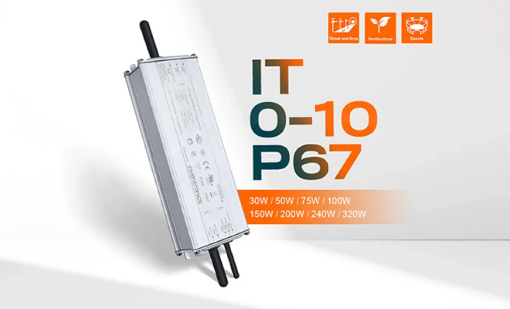
Inventronics has announced two new additions to its outdoor LED driver portfolio: the 150W IT 0-10 150/100-277 P67 and the 240W IT 0-10 240/100-277 P67 programmable drivers. With this new series, the company aims to establish a new benchmark in street and area lighting in terms of performance, efficiency, and durability.
5 kW GaN-Based AC/DC Reference Design from EPC for AI Servers and Data Centers EL SEGUNDO, California — October 2025 — Efficient Power Conversion Corporation (EPC), the world leader in enhancement-mode gallium nitride (eGaN®) power devices, has announced a high-efficiency, high-power-density 5 kW AC-to-48 V DC GaN reference design developed to meet the demands of AI servers and next-generation data center power architectures.
Sensirion has officially announced its next-generation SEN65 and SEN63C sensor platforms, designed to make indoor air quality measurement easier and more accurate than ever before. In addition, the SEK-SEN63C evaluation kit is now available for purchase, enabling developers and system integrators to quickly test and evaluate the new sensor family. Initial orders can be placed immediately.
The long-awaited beta release of Vitis AI 5.1 from AMD has been announced, marking the beginning of a major architectural shift that significantly advances edge AI inference capabilities.
With 44 years of experience, Empa Elektronik, a trusted and pioneering company in the electronic components industry, is set to make transformative investments in the technology ecosystem through its collaboration with Fark Labs, a global innovation and transformation center.
In a comparative study of Auto-ML platforms designed to simplify edge AI deployment, NanoEdge AI Studio and Edge Impulse emerged as leading solutions [1]. The comparison was conducted using multi-sensor biomedical data applied to predictive maintenance use cases.
In shopping malls, galleries, and large-scale commercial spaces, the stability and intelligence of lighting systems are among the most critical factors directly influencing user experience.