A breadboard is an experiment board used to design and test electronic circuits without soldering. It allows temporary circuit connections to be tested practically, helping detect assembly or design errors before PCB manufacturing. If a fault is identified, improvements can be applied directly on the board. For detailed information about breadboards, you can continue reading this article.
How to Use a Breadboard
A breadboard works on a plug-and-play principle. You can insert components and build circuits quickly, remove them after testing, and reuse the same board repeatedly across different projects. Breadboards help save both time and cost during prototyping.
Breadboards include power rails marked with “+” and “−” for voltage supply connections. These rails distribute power to circuit components along the entire length of the board. The center area contains terminal strips organized into columns, typically grouped as 5-hole nodes. Each 5-hole column segment shares the same internal metal clip, enabling electrical continuity. These nodes are used to bridge component terminals and establish temporary circuit paths. Importantly, many breadboards split the power rails into two isolated halves in the center, meaning they are not short-circuited from end to end.
Internal Structure of a Breadboard
The internal structure consists of vertically and horizontally aligned conductive metal clips enclosed within insulated plastic housing. The red and blue outer sections represent power rail rows, offering uninterrupted conductivity along their axis. The central section contains column-based conductors, also housed in insulated plastic. The middle gap on a breadboard isolates the left and right terminal columns, preventing default short circuits between opposing sides.
Breadboard Sizes and Types
Breadboard types vary by size:
Mini and medium boards: Suitable for simple or moderately complex projects.
Large boards: Preferred for multi-component or complex circuit testing.
Users can select the most suitable breadboard size depending on project complexity and number of component terminals.
Circuit Examples on Breadboards
Series connections: Components must share continuity between adjacent terminal nodes to form a series path.
Parallel connections: Anode and cathode or “+” and “−” terminals of polarized components must be placed into the same column node group to enable parallel continuity.
IC connections: Integrated circuits are placed across the center gap so each pin occupies a dedicated column node. Inter-pin communication is achieved by bridging pin columns using jumper cables.
Simple LED circuit: Anode and cathode legs connect to power rails or shared columns to test voltage and continuity before full assembly.
Critical Rules When Building a Circuit on a Breadboard
To ensure correct and safe operation:
Do not insert multiple legs of the same component into the same column node—this will cause a short circuit.
Ensure component legs do not touch each other during wiring, especially for long-leg elements.
Never reverse polarity for polarized components such as capacitors.
If mounting tape is used on the back of the breadboard, avoid mechanical stress or damage when removing it.
What Should Be Avoided During Breadboard Circuit Setup
Direct contact between positive/negative legs in the same node
Cross-shorting across the center isolation gap
Incorrect orientation of polarized components
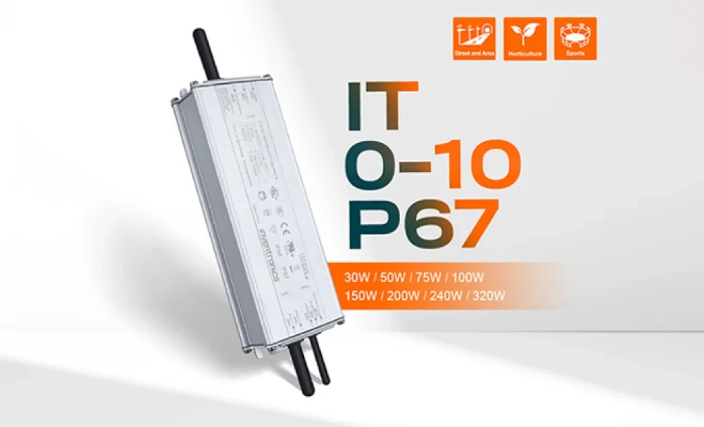
Inventronics has announced two new additions to its outdoor LED driver portfolio: the 150W IT 0-10 150/100-277 P67 and the 240W IT 0-10 240/100-277 P67 programmable drivers. With this new series, the company aims to establish a new benchmark in street and area lighting in terms of performance, efficiency, and durability.
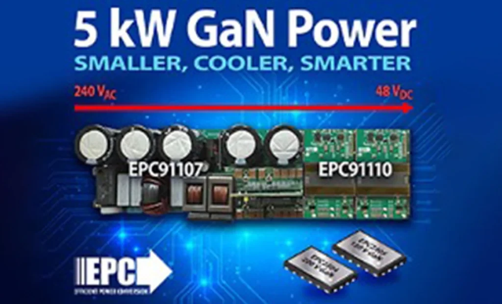
5 kW GaN-Based AC/DC Reference Design from EPC for AI Servers and Data Centers EL SEGUNDO, California — October 2025 — Efficient Power Conversion Corporation (EPC), the world leader in enhancement-mode gallium nitride (eGaN®) power devices, has announced a high-efficiency, high-power-density 5 kW AC-to-48 V DC GaN reference design developed to meet the demands of AI servers and next-generation data center power architectures.
Sensirion has officially announced its next-generation SEN65 and SEN63C sensor platforms, designed to make indoor air quality measurement easier and more accurate than ever before. In addition, the SEK-SEN63C evaluation kit is now available for purchase, enabling developers and system integrators to quickly test and evaluate the new sensor family. Initial orders can be placed immediately.
The long-awaited beta release of Vitis AI 5.1 from AMD has been announced, marking the beginning of a major architectural shift that significantly advances edge AI inference capabilities.
With 44 years of experience, Empa Elektronik, a trusted and pioneering company in the electronic components industry, is set to make transformative investments in the technology ecosystem through its collaboration with Fark Labs, a global innovation and transformation center.
In a comparative study of Auto-ML platforms designed to simplify edge AI deployment, NanoEdge AI Studio and Edge Impulse emerged as leading solutions [1]. The comparison was conducted using multi-sensor biomedical data applied to predictive maintenance use cases.
In shopping malls, galleries, and large-scale commercial spaces, the stability and intelligence of lighting systems are among the most critical factors directly influencing user experience.